Hi, this is the third post of a series where I explore the network connectivity between OCI and the exterior world using IPSec VPN. In the first post, I created two sites using Virtualbox and connected them using just Openswan, so not exactly OCI-related. In the second one, I used AWS with Openswan in one side, and OCI IPSec VPN in the other, thus connecting the two clouds. Now, what I’m going to do here is to use the IPSec VPN Tunnels and almost all the configuration created in the previous post, to not only connect to one VCN in OCI, but several, using OCI Transit Routing. This concept is explained in the OCI documentation here.
This tutorial is available in video as well here, in Portuguese only, to help Oracle community in Brazil.
I hope you enjoy.
Here is architecture I’m going to build:

Please note that the AWS side is exactly the same as we build in the previous post. On OCI, we have the same VCN_OS already created there, with its public Subnet, but now we will have two other Spoke VCNs. VCN_OS will act as our Hub VCN that will transit the traffic between AWS and the Spoke VCNs in both directions.
We will need to create some Local Peering Gateways as well, in order to connect the VCNs.
NOTE: If any command does not work due to privileges, it’s probably because you are not executing as root. For this to work, just put a “sudo” before the command, or issue “sudo su” to become root and then you can execute anything.
So, let’s start the process (or continue it).
1. Repeat initial steps to create the VPN Tunnel
All AWS steps and initial steps in OCI are the same as in my previous post Site-to-site IPSec VPN between AWS and OCI (with video).
I’m going to repeat here the steps starting at #13, when we create the CPE and IPSec Connection. So, I am skipping steps 1-12 and considering you have all that steps done correctly before continuing. If you never followed that steps, please do it before continuing.
If your VPN tunnels are still up and running OK, then you can safely skip directly to the step 8 of this post. Otherwise, if the tunnels are not working for any reason, just DELETE/TERMINATE the CPE and IPSec Connection and start here.
Make sure you write down all the IPs and secret keys. In my case I have at this moment:
Openswan Public IP: 18.220.224.1
Openswan Private IP: 10.1.0.41
Server1 Public IP: 3.128.34.39
Server1 Private IP: 10.1.0.199


2. Create a Customer Premise Equipment (CPE) and an IPSec Connection
Create the CPE with the name CPE_OS and associate it to the public IP of the Openswan in AWS (18.220.224.1). Select the vendor Libreswan (equivalent to Openswan) and the indicated version.

Create the IPSec connection with the name IPSEC_OS, attached to the CPE and DRG previously created. Use a static route with CIDR 10.1.0.0/16 (which is the AWS VPC’s CIDR).

Right after creating IPSec connection, you can already see the two redundant tunnels created:
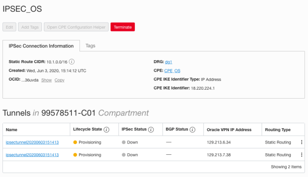
Write down their IPs and secret keys (to see the secret key, click on the tunnel and then Show beside Shared Secret), we will need them to configure Openswan:
Tunnel1 Public IP: 129.213.6.34
Tunnel1 Secret key: “2hE2oW8bfQXPZKlC84DUdf071V6KaXUYgsuiXlYk9oSGHYzsoYwQ8gvMJuPhpaTR”
Tunnel2 Public IP: 129.213.7.38
Tunnel2 Secret key: “7CcJXYUiKOayYB7c4p9czUQcLcFbtOFohA0fxvR79p8VnqOy8lrxjUIPKgnACVoz”
After a while, you will see both tunnels as available, but with the IPSec status still Down. This status will change to Up only when both sides are configured properly.
3. Configure IPSEC in Openswan VM
Now that you have all the IPs and resources required to configure the tunnels, you can come back to you Openswan VM in AWS and configure it.
Create or adjust the file /etc/ipsec.d/oci-ipsec.conf with the following content:
conn oracle-tunnel-1
	left=10.1.0.41
	leftid=18.220.224.1 # See preceding note about 1-1 NAT device
	right=129.213.6.34
	authby=secret
	leftsubnet=0.0.0.0/0
	rightsubnet=0.0.0.0/0
	auto=start
	mark=5/0xffffffff # Needs to be unique across all tunnels
	vti-interface=vti1
	vti-routing=no
	ikev2=no # To use IKEv2, change to ikev2=insist
	ike=aes_cbc256-sha2_384;modp1536
	phase2alg=aes_gcm256;modp1536
	encapsulation=yes
	ikelifetime=28800s
	salifetime=3600s
conn oracle-tunnel-2
	left=10.1.0.41
	leftid=18.220.224.1 # See preceding note about 1-1 NAT device
	right=129.213.7.38
	authby=secret
	leftsubnet=0.0.0.0/0
	rightsubnet=0.0.0.0/0
	auto=start
	mark=6/0xffffffff # Needs to be unique across all tunnels
	vti-interface=vti2
	vti-routing=no
	ikev2=no # To use IKEv2, change to ikev2=insist
	ike=aes_cbc256-sha2_384;modp1536
	phase2alg=aes_gcm256;modp1536
	encapsulation=yes
	ikelifetime=28800s
	salifetime=3600s
Remember: left parameters refer to the local network (the AWS VPC_OS), and right parameters refer to the remote network (the OCI VCN_OS).
Make sure to adjust the following parameters according to your specific IPs:
left: Openswan private IP
leftif: Openswan public IP
right: tunnel1 and tunnel2 IPs (put one on each “conn” block)
ATTENTION: ensure that the indentation won’t be lost in the copy / paste process, otherwise you will have problems.

4. Configure the secret keys file in Openswan VM
Create or adjust the file /etc/ipsec.d/oci-ipsec.secrets with the following content:
18.220.224.1 129.213.6.34: PSK “2hE2oW8bfQXPZKlC84DUdf071V6KaXUYgsuiXlYk9oSGHYzsoYwQ8gvMJuPhpaTR”
18.220.224.1 129.213.7.38: PSK “7CcJXYUiKOayYB7c4p9czUQcLcFbtOFohA0fxvR79p8VnqOy8lrxjUIPKgnACVoz”

5. Restart IPSec in Openswan VM
sudo systemctl enable ipsec.service
sudo systemctl restart ipsec.service
sudo systemctl status ipsec.service

6. Check the tunnel status
If the tunnel is working, you should see two vti interfaces on the Openswan VM:
ifconfig | grep vti

And let’s check if the connection between the two sides has been established:
sudo ipsec status | grep established
Note that Openswan shows the two tunnels are already active and with the connections established:

If you do not get any results from the above command, even if you wait a few minutes, it is likely that something was wrong with the configuration.
After Openswan shows the connection has been established, wait a little longer and the OCI console should also show the tunnels are finally up:

7. Add the proper routes in Openswan VM
Please note that we need to add the routes for all the networks we want to access in the target site:
ip route add 10.0.0.0/16 nexthop dev vti1 nexthop dev vti2
ip route add 10.2.0.0/16 nexthop dev vti1 nexthop dev vti2
ip route add 10.3.0.0/16 nexthop dev vti1 nexthop dev vti2
Remember that these routes won’t be persistent. You would need to re-add them every time your instance boot, or alternatively you can make them persistent by adding the following rows into /etc/sysconfig/network-scripts/route-eth0:
10.0.0.0/16 nexthop dev vti1 nexthop dev vti2
10.2.0.0/16 nexthop dev vti1 nexthop dev vti2
10.3.0.0/16 nexthop dev vti1 nexthop dev vti2
8. Create a Bastion instance in OCI
In our new architecture, the VCN_OS network (which will be our Hub VCN) will have only the Bastion host. We will be able to access it via SSH and from there reach all the other servers in OCI.
If you still have the server2 created in our previous architecture, just terminate it.
Let’s create the Bastion instance in the public subnet of our VCN_OS. Don’t forget to upload your public key so you can connect via SSH later. Remember that this Subnet is using the Route Table PubRT and Security List PubSL created in our previous post.

When the instance is provisioned, write down its IPs as well:
Bastion Public IP: 193.122.166.22
Bastion Private IP: 10.0.0.3
9. Access Bastion via PING and SSH
ping 193.122.166.22
ssh -i ~/.ssh/ocikey opc@193.122.166.22

10. Test ping between Server1 and Bastion
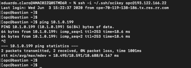
If your tunnels are up and you added the proper route in Openswan VM, the ping between Server1 (in AWS) and Bastion (in OCI) should work through their private IPs:
ssh -i ~/.ssh/awskey.pem ec2-user@3.128.34.39
ping 10.0.0.3

ssh -i ~/.ssh/ocikey opc@193.122.166.22
ping 10.1.0.199
11. Test SSH between Server1 and Bastion
Before testing SSH, we need to copy the private keys into the servers.
Let’s copy the OCI private key into Server1 on AWS, and the AWS private key into Bastion on OCI.
scp -i ~/.ssh/awskey.pem ~/.ssh/ocikey ec2-user@3.128.34.39:~/.ssh
scp -i ~/.ssh/ocikey ~/.ssh/awskey.pem opc@193.122.166.22:~/.ssh

Now let’s try to connect to Server1, and from there do SSH to Bastion (using its private IP):
ssh -i ~/.ssh/awskey.pem ec2-user@3.128.34.39
# ssh -i ~/.ssh/ocikey opc@10.0.0.3

And let’s do the opposite test as well, connecting to Bastion first and then doing SSH to Server1 (using its private IP):
ssh -i ~/.ssh/ocikey opc@193.122.166.22
# ssh -i ~/.ssh/awskey.pem ec2-user@10.1.0.199

12. Create the two Spoke VCNs
Now, lets start creating new stuff. As you can see in our architecture design, we will have two more VCNs in OCI, the spoke VCNs that will take advantage of the IPSec VPN to communicate to the “on-premise” (actually AWS) site.
For these two VCNs we will leverage the default Route Table and default Security List of each one, in order to simplify the process.
Create the VCNs with the following parameters:
VCN Spoke1, CIDR 10.2.0.0/16, and a private subnet PrivSpoke1 with CIDR 10.2.0.0/24.
VCN Spoke2, CIDR 10.3.0.0/16, and a private subnet PrivSpoke2 with CIDR 10.3.0.0/24.


13. Create the server Serversp1 and Serversp2
Let’s now create two VM instances in OCI, named Serversp1 and Serversp2, inside Subnets PrivSpoke1 and PrivSpoke2 respectively. Please note these two instances will have only a private IP, so the only way to connect to them via SSH is to access the Bastion host first, and from there jump to Serversp1 or Serversp2. Don’t forget to upload your OCI key when creating the instances.


Let’s write down their IPs:
Serversp1 Private IP:
Serversp2 Private IP:
14. Peer the VCNs
In order for the VCNs to be able to communicate, we need to attach them by using Local Peering Gateways (LPG), because they are in the same region (if they were in different regions we would need to use DRG to establish a Remote Peering Connection).
So, we will need to create two LPGs within VCN_OS, and one within each Spoke1 and SPoke2 VCNs. I will name then LPG_OS_Spoke1, LPG_OS_Spoke2, LPG_Spoke1_OS and LPG_Spoke2_OS respectively.
After creating them, establish the Peering Connections properly, according to our design:
VCN_OS / LPG_OS_Spoke1 <===> Spoke1 / LPG_Spoke1_OS
VCN_OS / LPG_OS_Spoke2 <===> Spoke2 / LPG_Spoke2_OS
Please note that you can establish the peer from any side, he result will be the same.

15. Create all the required routing rules
Well, the next two steps are maybe the trickiest ones. We need to create a lot of routing rules and route tables, not only in OCI, but adjust some things in AWS as well.
Instead of describing every rule we have to create, which would be very boring, I’m gonna put here a slide with each and every Route Table we will have, and the rules required in each one:

15.1. Adjust the routing rules in AWS
Let’s start with the AWS part, in purple in the slide. You already have the PubRT_OS route table, so include the route rules for the two new VCNs (10.2 and 10.3).

15.2. Create a Route Table for the DRG
Now, back to OCI, let’s create the Routing Table for the DRG named DRG_RT and with the following rules:

15.3. Adjust the routing rules in the VCN_OS public subnet
Let’s proceed to the Route Table PubRT attached to the Public Subnet of VCN_OS. It already exists, but make sure to add the rules that will route traffic to the LPGs:

15.4. Create the Route Table for the LPG_OS_Spoke1 in the VCN_OS
Now, still in the VCN_OS, create the Route Table RT_LPG_OS_Spoke1 with the following rules:

15.5. Create the Route Table for the LPG_OS_Spoke2 in the VCN_OS
Do the same again to create the Route Table RT_LPG_OS_Spoke2 with the following rules:

15.6. Attach the new Route Tables to the DRG and LPGs
First attach DRG_RT to your DRG: from within your VCN_OS, click Dynamic Routing Gateway, then click on the three dots beside the DRG and choose Associate Route Table:

Then, do the same for both LPGs:

15.7. Adjust the Spoke1 VCN Default Route Table
As you remember, I opted to use the default route table and security list for both spoke VCNs. So, adjust the default route table of the Spoke1 VCN to have the following rules:

15.8. Adjust the Spoke2 VCN Default Route Table
Similarly, adjust the default route table of the Spoke2 VCN to have the following rules:

16. Create all the required firewall (Security Lists / Groups) rules
I also prepared a slide to show all the Security Lists that need to be created or adjusted:

Please note that I am showing only ingress rules. For the egress, we will just allow all traffic.
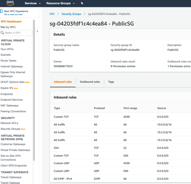
16.1. Adjust Security Group rules in AWS
In AWS we need to include ingress rules for the two new VCNs we’ve created in OCI. Then the PublicSG Security Group will have the following rules:
16.2. Adjust Security List PubSL in VCN_OS
Let’s now adjust the Security List being used by our public Subnet in VCN_OS, by adding the ingress rules for the two new VCNs:

16.3. Adjust the Spoke1’s Default Security List
In Spoke1 I’ll just allow all the incoming traffic from the other spoke VCN and the AWS VPC as well:

16.4. Adjust the Spoke2’s Default Security List
Let’s do the same in Spoke2:

17. Test the connectivity among the networks
17.1 Test connectivity between the Hub VCN (VCN_OS) and the spoke VCNs
Let’s see if the LPGs are working properly, trying to communicate between the Bastion host in VCN_OS and the two spoke VCNs:
scp -i ~/.ssh/ocikey ~/.ssh/ocikey opc@193.122.166.22:~/.ssh
ssh -i ~/.ssh/ocikey opc@193.122.166.22
ping 10.2.0.2
ping 10.3.0.2
ssh -i ~/.ssh/ocikey opc@10.2.0.2
exit
ssh -i ~/.ssh/ocikey opc@10.3.0.2

17.2 Test connectivity between the Hub VCN and AWS
scp -i ~/.ssh/ocikey ~/.ssh/awskey.pem opc@193.122.166.22:~/.ssh
ssh -i ~/.ssh/ocikey opc@193.122.166.22
ping 10.1.0.41
ping 10.1.0.199
ssh -i ~/.ssh/awskey.pem ec2-user@10.1.0.199

17.3 Test connectivity between a spoke VCN and AWS
ssh -i ~/.ssh/ocikey opc@193.122.166.22
scp -i ~/.ssh/ocikey ~/.ssh/awskey.pem opc@10.2.0.2:~/.ssh
ssh -i ~/.ssh/ocikey opc@10.2.0.2
ping 10.1.0.199
ssh -i ~/.ssh/awskey.pem ec2-user@10.1.0.199

To finish, it’s important to say that the Spoke VCNs cannot communicate with each other. If you wanted to allow that, you should create a new LPG in Spoke1 and Spoke2, connect them with each other, and add the proper rules in their Route Tables and Security Lists.
You may imagine, like I did, that simply creating a route rule in the route tables attached to the LPGs in the Hub VCN, pointing to the other LPG, would do the job. It would be something like this:

But no, it doesn’t work. Oracle does not allow us to create a LPG-type rule in a Route Table attached to another LPG. See what happens if I try (note the red error message at the bottom-right of the screen):

I don’t see a reason for it not to be allowed, but it is what it is right?
That’s it.
I hope you have enjoyed this long journey again. If you do, please let your comment, it’s important. Let me know if you have any doubt as well.
Thanks and see you later!
OCI Transit Routing (com vídeo)
Olá, este é o terceiro post de uma série onde eu exploro as capacidades de conectividade entre a OCI e o mundo exterior usando IPSec VPN. No primeiro post, eu criei dois sites usando Virtualbox e os conectei usando Openswan, então não é diretamente relacionado com OCI. No segundo, usei AWS com Openswan de um lado, e o serviço IPSec VPN no outro, conectando assim as duas clouds. Agora, o que vou fazer aqui é usar os túneis IPSec e quase toda a configuração criada no post anterior, para não só conectar a uma VCN na OCI, mas a várias, usando OCI Transit Routing. Este conceito é explicado na documentação da OCI aqui.
Este tutorial está disponível também em vídeo aqui, em Português somente, para ajudar a comunidade Oracle no Brasil.
Espero que gostem.
Aqui está a arquitetura que vou construir:
Veja que no lado da AWS a configuração é exatamente a mesma construída no post anterior. Na OCI, nós temos a mesma VCN_OS já criada, com sua subnet pública, mas agora teremos também duas “spoke” VCNs. A VCN_OS fará o papel de VCN Hub that will direcionar o tráfego entre a AWS e as Spoke VCNs em ambas as direções.
Teremos que criar também alguns Local Peering Gateways, para permitir a conexão entre as VCNs.
NOTA: se algum comando não funcionar por causa de privilégios, é provável que você não está executando como root. Para funcionar, apenas coloque “sudo” antes do comando, ou então execute “sudo su” pra se tornar root e então você poderá rodar qualquer comando.
Então vamos começar (ou continuar).
1. Repita os passos inicias para criar o túnel VPN
Todos os passos da AWS e os passos iniciais da OCI são os mesmos que em meu post Site-to-site IPSec VPN between AWS and OCI (with video).
Vou repetir aqui os passos a partir do #13, onde criamos o CPE e a conexão IPSec. Portanto, estou pulando os passos 1-12 e considerando que você tenha todos os passos executados corretamente antes de continuar. Se você nunca seguiu os passos daquele post, faça isso antes de continuar aqui.
Se seus túneis VPN estão no ar e funcionando OK, então você pode seguramente pular para o passo 8 deste post. Por outro lado, se os túneis não estiverem funcionando por qualquer razão, destrua o CPE e a conexão IPSec, e comece por aqui.
Anote os IPs e chaves secretas dos elementos da sua arquitetura. No meu caso eu tenho até o momento:
Openswan IP público: 18.220.224.1
Openswan IP privado: 10.1.0.41
Server1 IP público: 3.128.34.39
Server1 IP privado: 10.1.0.199
2. Crie um Customer Premise Equipment (CPE) e uma Conexão IPSec
Crie o CPE com o nome CPE_OS e associe-o ao IP público da VM Openswan na AWS (18.220.224.1). Selecione o vendor Libreswan (equivalente ao Openswan) e a versão indicada.
Crie a conexão IPSec com o nome IPSEC_OS, ligada ao CPE e ao DRG criados anteriormente. Use uma rota estática com o CIDR 10.1.0.0/16 (que é o CIDR da VPC AWS).
Depois de criar a conexão IPSec, você já pode ver os dois túneis redundantes criadas:
Anote os IPs e chaves secretas (pra ver a chave secreta, clique no túnel e então em Show beside Shared Secret), vamos precisar deles pra configurar o Openswan:
Tunnel1 IP público: 129.213.6.34
Tunnel1 Chave secreta: “2hE2oW8bfQXPZKlC84DUdf071V6KaXUYgsuiXlYk9oSGHYzsoYwQ8gvMJuPhpaTR”
Tunnel2 IP público: 129.213.7.38
Tunnel2 Chave secreta: “7CcJXYUiKOayYB7c4p9czUQcLcFbtOFohA0fxvR79p8VnqOy8lrxjUIPKgnACVoz”
Depois de alguns minutos, você verá os túneis como disponíveis, mas com o status do IPSec ainda Down. Este status vai mudar para Up somente quando os dois lados estiverem propriamente configurados.
3. Configure o IPSEC na VM Openswan
Agora que você tem todos os IPs e recursos necessários para configurar os túneis, você pode voltar para a VM Openswan na AWS e configurá-la.
Crie ou ajuste o arquivo /etc/ipsec.d/oci-ipsec.conf com o seguinte conteúdo:
conn oracle-tunnel-1
	left=10.1.0.41
	leftid=18.220.224.1 # See preceding note about 1-1 NAT device
	right=129.213.6.34
	authby=secret
	leftsubnet=0.0.0.0/0
	rightsubnet=0.0.0.0/0
	auto=start
	mark=5/0xffffffff # Needs to be unique across all tunnels
	vti-interface=vti1
	vti-routing=no
	ikev2=no # To use IKEv2, change to ikev2=insist
	ike=aes_cbc256-sha2_384;modp1536
	phase2alg=aes_gcm256;modp1536
	encapsulation=yes
	ikelifetime=28800s
	salifetime=3600s
conn oracle-tunnel-2
	left=10.1.0.41
	leftid=18.220.224.1 # See preceding note about 1-1 NAT device
	right=129.213.7.38
	authby=secret
	leftsubnet=0.0.0.0/0
	rightsubnet=0.0.0.0/0
	auto=start
	mark=6/0xffffffff # Needs to be unique across all tunnels
	vti-interface=vti2
	vti-routing=no
	ikev2=no # To use IKEv2, change to ikev2=insist
	ike=aes_cbc256-sha2_384;modp1536
	phase2alg=aes_gcm256;modp1536
	encapsulation=yes
	ikelifetime=28800s
	salifetime=3600s
Relembrando: os parâmetros left se referem ao site local (a VPC_OS na AWS), e os parâmetros right se referem ao site remoto (a VCN_OS na OCI).
Ajuste os seguintes parâmetros de acordo com os seus IPs:
left: IP privado do Openswan
leftif: IP público do Openswan
right: IPs dos tunnel1 e tunnel2 (coloque um em cada bloco “conn”)
ATENÇÃO: garanta que a indentação não será perdida no copy / paste, senão você terá problemas.
4. Configure as chaves secretas na VM Openswan
Crie ou ajuste o arquivo /etc/ipsec.d/oci-ipsec.secrets com o seguinte conteúdo:
18.220.224.1 129.213.6.34: PSK “2hE2oW8bfQXPZKlC84DUdf071V6KaXUYgsuiXlYk9oSGHYzsoYwQ8gvMJuPhpaTR”
18.220.224.1 129.213.7.38: PSK “7CcJXYUiKOayYB7c4p9czUQcLcFbtOFohA0fxvR79p8VnqOy8lrxjUIPKgnACVoz”
5. Reinicie IPSec na VM Openswan
sudo systemctl enable ipsec.service
sudo systemctl restart ipsec.service
sudo systemctl status ipsec.service
6. Verifique o status do túnel
Se o túnel estiver funcionando, você deverá ver duas interfaces vti na VM Openswan:
ifconfig | grep vti
E vamos verificar se a conexão entre os dois lados foi estabelecida:
sudo ipsec status | grep established
Note que o Openswan mostra que os dois túneis já estão ativos e com a conexão estabelecida:
Se você não receber nenhum resultado do comando acima, mesmo após esperar alguns minutos, é provável que você errou em alguma configuração.
Depois que o Openswan mostrar as conexões estabelecidas, espero um pouco mais e o console OCI deve também mostrar os túneis finalmente Up:
7. Adicione as rotas necessárias na VM Openswan
Note que vamos adicionar rota para todas as redes que queremos acessar no site remot (OCI):
ip route add 10.0.0.0/16 nexthop dev vti1 nexthop dev vti2
ip route add 10.2.0.0/16 nexthop dev vti1 nexthop dev vti2
ip route add 10.3.0.0/16 nexthop dev vti1 nexthop dev vti2
Lembre-se que essas rotas não são persistentes. Toda vez que você reiniciar a VM precisará readicionar as rotas. Alternativamente, você pode fazê-las persistentes adicionando as seguintes linhas no arquivo /etc/sysconfig/network-scripts/route-eth0:
10.0.0.0/16 nexthop dev vti1 nexthop dev vti2
10.2.0.0/16 nexthop dev vti1 nexthop dev vti2
10.3.0.0/16 nexthop dev vti1 nexthop dev vti2
8. Crie um Bastion host na OCI
Nesta nova arquitetura, a VCN_OS (que será nossa VCN Hub) terá somente este Bastion host. Vamos acessá-lo através de SSH e a partir dele poderemos acessar todos os outros servidores na OCI.
Se você ainda tem o server2 criado na arquitetura prévia, destrua-a.
Vamos criar a VM Bastion na subnet pública da sua VCN_OS. Não se esqueça de fazer o upload do sua chave pública para poder se conectar via SSH depois. Lembre que essa Subnet está usando a Route Table PubRT e a Security List PubSL criadas anteriormente.
Quando a VM estiver provisionada, anote os IPs dela:
Bastion IP público: 193.122.166.22
Bastion IP privado: 10.0.0.3
9. Accesse o Bastion via PING e SSH
ping 193.122.166.22
ssh -i ~/.ssh/ocikey opc@193.122.166.22
10. Teste o ping entre o Server1 e o Bastion
Se o seu túnel está no ar e voce adicionou as rotas adequadamente na VM Openswan, o ping entre o Server1 (na AWS) e o Bastion (na OCI) deve funcionar pelos IPs privados:
ssh -i ~/.ssh/awskey.pem ec2-user@3.128.34.39
ping 10.0.0.3
ssh -i ~/.ssh/ocikey opc@193.122.166.22
ping 10.1.0.199
11. Teste o SSH entre o Server1 e o Bastion
Antes de testar o SSH, precisamos copiar as chaves privadas para os servidores.
Vamos copiar a chave privada da OCI para dentro do Server1 na AWS, e a chave privada da AWS para dentro do Bastion na OCI.
scp -i ~/.ssh/awskey.pem ~/.ssh/ocikey ec2-user@3.128.34.39:~/.ssh
scp -i ~/.ssh/ocikey ~/.ssh/awskey.pem opc@193.122.166.22:~/.ssh
Agora vamos tentar conectar no Server1, e de lá fazer SSH para o Bastion (usando seu IP privado):
ssh -i ~/.ssh/awskey.pem ec2-user@3.128.34.39
# ssh -i ~/.ssh/ocikey opc@10.0.0.3
E vamos fazer o caminho inverso também, conectando no Bastion primeiro e de lá fazer o SSH para o Server1 (usando seu IP privado):
ssh -i ~/.ssh/ocikey opc@193.122.166.22
# ssh -i ~/.ssh/awskey.pem ec2-user@10.1.0.199
12. Crie as duas Spoke VCNs
Agora vamos começar a criar elementos novos. Como você pode ver no desenho da arquitetura, teremos duas novas VCNs na OCI, as spoke VCNs que aproveitarão o túnel IPSec pra se comunicar com o ambiente “on-premise” (na verdade a AWS).
Para estas duas VCNs vamos aproveitar a Route Table e a Security List default de cada uma das redes, para simplificar o processo.
Crie as VCNs conforme abaixo:
VCN Spoke1, CIDR 10.2.0.0/16, e uma subnet privada PrivSpoke1 com CIDR 10.2.0.0/24.
VCN Spoke2, CIDR 10.3.0.0/16, e uma subnet privada PrivSpoke2 com CIDR 10.3.0.0/24.
13. Crie os servidores Serversp1 e Serversp2
Vamos criar duas VMs com os nomes Serversp1 and Serversp2, nas subnets PrivSpoke1 and PrivSpoke2 respectivamente. Veja que estas instâncias terão somente IPs privados, portanto a única maneira de acessá-las via SSH será através do Bastion host. Não se esqueça de fazer o upload da sua chave ao criar as VMs.
Vamos anotar os IPs:
Serversp1 IP privado:
Serversp2 IP privado:
14. Ligue as VCNs
Para que as VCNs possam se comunicar, precisamos ligá-las usando Local Peering Gateways (LPG), porque elas estão na mesma região (se estivessem em regiões diferentes, precisaríamos usar um DRG pra estabelecer Remote Peering Connection).
Vamos precisar de dois LPGs na VCN_OS, e mais um nas VCNs Spoke1 e SPoke2. Vou nomeá-los como LPG_OS_Spoke1, LPG_OS_Spoke2, LPG_Spoke1_OS e LPG_Spoke2_OS respectivamente.
Depois de criá-los, estabeleça as conexões de acordo com o nosso desenho:
VCN_OS / LPG_OS_Spoke1 <===> Spoke1 / LPG_Spoke1_OS
VCN_OS / LPG_OS_Spoke2 <===> Spoke2 / LPG_Spoke2_OS
Note que você pode estabelecer a conexão a partir de qualquer lado, o resultado será o mesmo.
15. Crie todas as regras de roteamento
Bom, os próximos dois passos são talvez os mais cansativos. Precisaremos criar um monte de regras de roteamento, não somente na OCI, mas também ajustar algumas na AWS.
Ao invés de descrever cada regra, o que seria muito tedioso, eu vou colocar um slide mostrando todas as Route Tables e as regras em cada uma:
15.1. Ajuste as regras de roteamento na AWS
Vamos começar com a parte na AWS, em roxo no slide. Voc6e já tem lá a route table PubRT_OS, então inclua as regras para as duas novas VCNs (10.2 and 10.3).
15.2. Crie uma Route Table para o DRG
Agora, de volta ao OCI, vamos criar uma Route Table para o DRG com o nome DRG_RT e as seguintes regras:
15.3. Ajuste as regras de roteamento na subnet pública da VCN_OS
Vamos continuar com a Route Table PubRT ligada à subnet pública da VCN_OS. Ela já existe, mas tenha certeza de adicionar as regras para direcionar o tráfego para os LPGs:
15.4. Crie a Route Table para o LPG_OS_Spoke1 na VCN_OS
Ainda na VCN_OS, crie a Route Table RT_LPG_OS_Spoke1 com as seguintes regras:
15.5. Crie a Route Table para LPG_OS_Spoke2 na VCN_OS
Crie a Route Table RT_LPG_OS_Spoke2 com as seguintes regras:
15.6. Ligue as novas Route Tables com o DRG e os LPGs
Primeiro ligue a DRG_RT to your DRG: na VCN_OS, clique en Dynamic Routing Gateway, te depois nos três pontos do lado do DRG e escolha Associate Route Table:
Faça o mesmo para os dois LPGs:
15.7. Ajuste a Default Route Table da VCN Spoke1
Como eu comentei antes, decidi usar a default route table e a default security list para as spoke VCNs. Então, ajuste a default route table da VCN Spoke1 para ter as seguintes regras:
15.8. Ajuste a Default Route Table da VCN Spoke2
Da mesma maneira, ajuste a default route table da VCN Spoke2 para ter as seguintes regras:
16. Crie todas as regras de firewall (Security Lists / Groups)
Eu também preparei um slide para mostrar todas as Security Lists e Security Groups que serão criados ou ajustados:
Note que estou mostrando apenas as regras de entrada. Para saída, vamos permitir todo o tráfego em todas as listas.
16.1. Ajuste a Security Group na AWS
Na AWS precisamos incluir as regas de entrada para as duas novas VCNs que criamos na OCI. A PublicSG deve ter as seguintes regras:
16.2. Ajuste a Security List PubSL na VCN_OS
Vamos agora ajustar a Security List being usada pela subnet pública na VCN_OS, adicionando as regras de entrada para as duas novas VCNs:
16.3. Ajuste a Default Security List da VCN Spoke1
Na VCN Spoke1 eu vou permitir todo o tráfego vindo da outra spoke VCN e a VPC AWS também:
16.4. Ajuste a Default Security List da VCN Spoke2
Na VCN Spoke2 vamos fazer a mesma coisa:
17. Teste a comunicação entre as redes
17.1 Teste a comunicação entre a Hub VCN (VCN_OS) e as spoke VCNs
Vamos ver se os LPGs estão funcionando, tentando a comunicação entre o Bastion host na VCN_OS e as duas spoke VCNs:
scp -i ~/.ssh/ocikey ~/.ssh/ocikey opc@193.122.166.22:~/.ssh
ssh -i ~/.ssh/ocikey opc@193.122.166.22
ping 10.2.0.2
ping 10.3.0.2
ssh -i ~/.ssh/ocikey opc@10.2.0.2
exit
ssh -i ~/.ssh/ocikey opc@10.3.0.2
17.2. Teste a comunicação entre a Hub VCN and AWS
scp -i ~/.ssh/ocikey ~/.ssh/awskey.pem opc@193.122.166.22:~/.ssh
ssh -i ~/.ssh/ocikey opc@193.122.166.22
ping 10.1.0.41
ping 10.1.0.199
ssh -i ~/.ssh/awskey.pem ec2-user@10.1.0.199
17.3 Teste a comunicação entre uma spoke VCN and AWS
ssh -i ~/.ssh/ocikey opc@193.122.166.22
scp -i ~/.ssh/ocikey ~/.ssh/awskey.pem opc@10.2.0.2:~/.ssh
ssh -i ~/.ssh/ocikey opc@10.2.0.2
ping 10.1.0.199
ssh -i ~/.ssh/awskey.pem ec2-user@10.1.0.199
Pra terminar, é importante dizer que as Spoke VCNs não conseguem se comunicar entre si. Se você quiser permitir isso, terá que criar novos LPGs nas spoke VCNs, ligá-los e criar as regras de roteamento e firewall.
Você pode imaginar, como eu fiz, que bastaria criar rotas de roteamento entre os dois LPGs da VCN_OS (a Hub), apontando um para o outro. Seria algo assim:
Mas não, isso não funciona. A OCI não permite que nós criemos uma regra do tipo LPG dentro de uma Route Table que está associada a outro LPG. Veja o que acontece se eu tento (note a mensagem de erro em vermelho no canto inferior direito):
Não entendo porque isso não é permitido, mas é assim.
Bom, é isso!
Espero que você tenha gostado de mais esse post enorme. Deu um enorme trabalho, mas sempre vale a pena.
Se você gostou, por favor deixe seu comentário. É importante!
Me avise se tiver dúvidas também.
Obrigado e até a próxima.
